NAT Virtual Interfaces (NVIs) and VRFs
This post is organized as:
- Description of legacy (domain-based) NAT and NAT Virtual Interface (NVI)
- Regular VRF routing without NAT
- Scenarios
- VRF to Global NVI NAT
- Global to VRF NVI NAT
- VRF to VRF NVI NAT
NAT operation with VRFs in Cisco IOS and IOS-XE are implemented using different software constructs.
A simple implementation of NAT on a Cisco IOS router can be configured using a domain-based NAT approach. In the topology below, Gi0/0 can be defined as inside interface and Gi0/2 as outside interface. Afterwards, a simple NAT rule can be put in place as required.
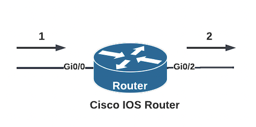
interface GigabitEthernet0/0
 ip nat inside
!
interface GigabitEthernet0/2
 ip nat outside
NAT behavior for traffic entering via Gi0/0 (inside) and flowing out of Gi0/2 (outside) would operate as:
- Traffic enters Gi0/0. A routing lookup is performed. Then, NAT translaton rule is consulted.
- Return traffic entering Gi0/2 would be NAT translated. Then, a lookup will be performed to route the resulting packet.
In Cisco IOS-XE, the software construct that makes inter-VRF NAT possible is VRF-Aware Software Infrastructure (VASI) NAT. This is not the direct topic of this post but many of the equivalent concepts described here for IOS apply.
In Cisco IOS with VRFs, NAT Virtual Interface (NVI) is created to facilitate the translation process between VRFs.
Using NVIs, translation is performed after route lookup decision is made. NVI = route lookup first, NAT next.
Consider the following topology.
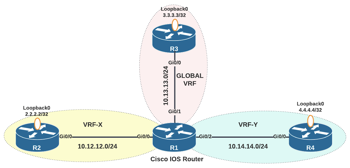
In this topology, there are three VRFs that segment router R1 into three virtually distinct routing tables. These logical segmentations can be visualized as depicted below. What occurs in the white space to link the routing tables is the routing and NAT software logic we're interested in.
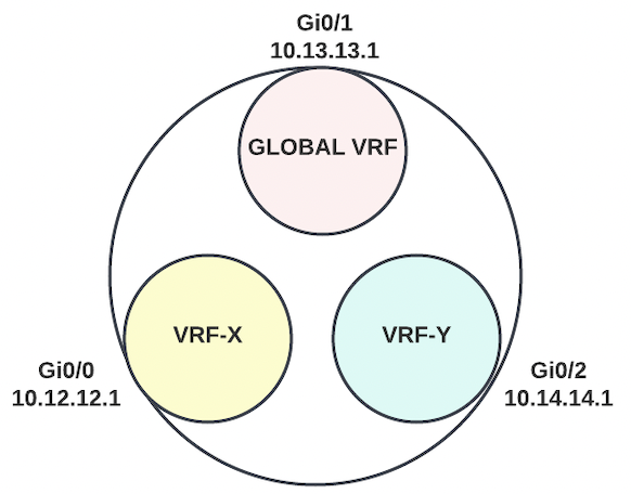
On R1, Gi0/0 is a member of VRF-X routing table, Gi0/1 is a member of the global routing table, and Gi0/2 is a member of VRF-Y.
R1
ip vrf VRF-X
!
ip vrf VRF-Y
!
interface GigabitEthernet0/0
 ip vrf forwarding VRF-X
 ip address 10.12.12.1 255.255.255.0
!
interface GigabitEthernet0/1
 ip address 10.13.13.1 255.255.255.0
!
interface GigabitEthernet0/2
 ip vrf forwarding VRF-Y
 ip address 10.14.14.1 255.255.255.0
!
The domain-based NAT approach is what Cisco recommends for VRF to global NAT. This is because it can take advantage of the inside-to-outside (route first, NAT next) and outside-to-inside (NAT first, route next) reversed operations. For example, when configuring Source NAT from 2.2.2.2 to 192.168.12.2:
- Original Traffic - Source IP: 2.2.2.2 Destination IP: 3.3.3.3
- Inside to Outside: Route lookup for destination 3.3.3.3. NAT 2.2.2.2 to 192.168.12.2
- Return Traffic: - Source IP: 3.3.3.3, Destination IP: 192.168.12.2
- Outside to Inside: NAT 192.168.12.2 to 2.2.2.2. Destination route lookup for 2.2.2.2
In this case, a route entry for 192.168.12.2 is not required to be in place. As long as a route for 2.2.2.2 exists in the proper VRF, the return traffic can be delivered.
The translation rule would look something like:
ip nat inside source static 2.2.2.2 192.168.12.2 vrf VRF-XWith Cisco IOS NVIs, routing lookup is done first before NAT translation rule is executed. This means return traffic routing is done based on the translated address.
- Original Traffic - Source IP: 2.2.2.2 Destination IP: 3.3.3.3
- Interface1 to Interface2: Route lookup for destination 3.3.3.3. NAT 2.2.2.2 to 192.168.12.2
- Return Traffic: - Source IP: 3.3.3.3, Destination IP: 192.168.12.2
- Interface2 to Interface1: Route lookup for destination 192.168.12.2. NAT 192.168.12.2 to 2.2.2.2
In this case, a route for 192.168.12.2 needs to exist in the proper VRF for full traffic path. The need to account for routes for translated IP address spaces can be a huge overhead in complex networks. Hence, Cisco's recommendation to use the legacy (inside/outside) NAT method for VRF to Global traffic.
For the routing lookup to consistently succeed for multiple types of traffic, the different VRFs need to have a way to communicate with each other. This may be achieved with regular static routing in small scale or more appropriately via route leaking using dynamic routing protocols.
There are a few select scenarios to look into. Some requirements to illustrate the behaviors:
- VRF-X to Global VRF NAT: Traffic from R2's Loopback0 (2.2.2.2) should be seen as 192.168.12.2 when it reaches R3's Loopback0 interface (3.3.3.3).
- Global VRF to VRF-Y NAT: Traffic from R3's Loopback0 (3.3.3.3) interface should be seen as 192.168.13.3 when it reaches R4's Loopback0 interface (4.4.4.4).
- VRF-X to VRF-Y NAT: Traffic from R2's Loopback0 (2.2.2.2) interface should be seen as 10.14.14.1 when it reaches R4's Loopback interface (4.4.4.4).
Routing on R2, R3, and R4 is setup using simple default routes to their linked next hops on R1.
R2
ip route 0.0.0.0 0.0.0.0 10.12.12.1
R3
ip route 0.0.0.0 0.0.0.0 10.13.13.1
R4
ip route 0.0.0.0 0.0.0.0 10.14.14.1
Regular Routing without NAT
First, verifying plain reachability without NAT to see how the isolated logical route tables need to be linked i.e. traffic sourced from R2's 2.2.2.2 destined to R3's 3.3.3.3.
Routing on R2 and R3 is as stated above a simple default route.
R2
ip route 0.0.0.0 0.0.0.0 10.12.12.1
R3
ip route 0.0.0.0 0.0.0.0 10.13.13.1
Routing on R1 on the other hand requires more considerations.
- Traffic sourced from R2's Loopback0 2.2.2.2 arrives on R1's interface Gi0/0 in VRF-X. This traffic is destined to 3.3.3.3. VRF-X needs to have a route for 3.3.3.3. The IP 3.3.3.3 can be reached via the global routing table and next hop 10.13.13.3 which is also in the gobal routing table.
R1
ip route vrf VRF-X 3.3.3.3 255.255.255.255 10.13.13.3 global
What the command above is doing is adding an entry in VRF-X routing table for destination 3.3.3.3 with next hop 10.13.13.3 in another VRF (global). Because 10.13.13.3 is also outside VRF-X, an additional recursive lookup is required to complete the forwarding.
R1#show ip route vrf VRF-X
~
Routing Table: VRF-X
~
      3.0.0.0/32 is subnetted, 1 subnets
S        3.3.3.3 [1/0] via 10.13.13.3
      10.0.0.0/8 is variably subnetted, 2 subnets, 2 masks
C        10.12.12.0/24 is directly connected, GigabitEthernet0/0
L 10.12.12.1/32 is directly connected, GigabitEthernet0/0- Traffic then reaches R3's Gi0/0 interface with source 2.2.2.2 and destination 3.3.3.3. The IP 3.3.3.3 is a locally connected interface Loopback0 on R3.
- On R3, return replies are generated from 3.3.3.3 destined to 2.2.2.2.
- This traffic then arrives on R1's Gi0/1 in the global routing table. Routing lookup is done for destination 2.2.2.2. But 2.2.2.2 is in VRF-X and R1 needs a way to link the global route table back to VRF-X.
R1
ip route 2.2.2.2 255.255.255.255 10.12.12.2
The next-hop 10.12.12.2 is also in VRF-X. Therefore, we also need to tell the global routing table the interface through which this next hop can recursively be reached i.e. via Gi0/0 in VRF-X.
R1
ip route 10.12.12.2 255.255.255.255 GigabitEthernet0/0
Enable "debug ip icmp" on R3. Ping should succeed and the IPs 2.2.2.2 and 3.3.3.3 will be communicating directly without translation.
R3#debug ip icmp
ICMP packet debugging is on
R2#ping 3.3.3.3 source 2.2.2.2 repeat 5
Type escape sequence to abort.
Sending 5, 100-byte ICMP Echos to 3.3.3.3, timeout is 2 seconds:
Packet sent with a source address of 2.2.2.2
!!!!!
Success rate is 100 percent (5/5), round-trip min/avg/max = 2/2/3 msReturn packets from R3's 3.3.3.3 to R2's 2.2.2.2
R3
* ICMP: echo reply sent, src 3.3.3.3, dst 2.2.2.2, topology BASE, dscp 0 topoid 0
* ICMP: echo reply sent, src 3.3.3.3, dst 2.2.2.2, topology BASE, dscp 0 topoid 0
* ICMP: echo reply sent, src 3.3.3.3, dst 2.2.2.2, topology BASE, dscp 0 topoid 0
* ICMP: echo reply sent, src 3.3.3.3, dst 2.2.2.2, topology BASE, dscp 0 topoid 0
* ICMP: echo reply sent, src 3.3.3.3, dst 2.2.2.2, topology BASE, dscp 0 topoid 0VRF-X to GLOBAL VRF NAT
Now, to test the NAT requirement add a NAT rule and enable NAT on the interfaces. Traffic from R2's Loopback0 (2.2.2.2) should be seen as 192.168.12.2 when it reaches R3's Loopback0 interface (3.3.3.3).
Cisco's NAT FAQ has the following to say regarding NAT NVI for VRF to global traffic.
Q. Should NAT NVI be used when NATting between an interface in global and an interface in a VRF?
A. Cisco recommends that you use legacy NAT for VRF to global NAT (ip nat inside/out) and between interfaces in the same VRF. NVI is used for NAT between different VRFs.
What behavior can be expected if we do not follow this recommendation?
R1
ip nat source static 2.2.2.2 192.168.12.2 vrf VRF-X
!
interface Gi0/0
ip nat enable
!
interface Gi0/1
ip nat enable
!If "ip nat enable" is not configured, traffic will just flow through unchanged and NAT will not be applied to it.
Validating interfaces on R1 shows that there is a new NVI interface created due to this configuraiton. The NVI inherited the IP address of the VRF-X interface Gi0/0.
R1#sh ip int br
Interface IP-Address OK? Method Status Protocol
GigabitEthernet0/0 10.12.12.1 YES manual up up
GigabitEthernet0/1 10.13.13.1 YES manual up up
GigabitEthernet0/2 10.14.14.1 YES manual up up
GigabitEthernet0/3 unassigned YES unset administratively down down
NVI0 10.12.12.1 YES unset up upEnsure that debug ip icmp is enabled on R1 and R3. Attempt to ping 3.3.3.3 from R2's 2.2.2.2. Pings will now fail.
R2#ping 3.3.3.3 source 2.2.2.2 repeat 5
Type escape sequence to abort.
Sending 5, 100-byte ICMP Echos to 3.3.3.3, timeout is 2 seconds:
Packet sent with a source address of 2.2.2.2
.....
Success rate is 0 percent (0/5)On R3, observe the output of debug ip icmp. Traffic from R2 is seen to reach R3. The traffic was source translated from 2.2.2.2 to 192.168.12.2 before getting to R3. Therefore, return packets are being sent back to 192.168.12.2 instead of 2.2.2.2.
R3#
* ICMP: echo reply sent, src 3.3.3.3, dst 192.168.12.2, topology BASE, dscp 0 topoid 0
* ICMP: echo reply sent, src 3.3.3.3, dst 192.168.12.2, topology BASE, dscp 0 topoid 0
* ICMP: echo reply sent, src 3.3.3.3, dst 192.168.12.2, topology BASE, dscp 0 topoid 0
* ICMP: echo reply sent, src 3.3.3.3, dst 192.168.12.2, topology BASE, dscp 0 topoid 0
* ICMP: echo reply sent, src 3.3.3.3, dst 192.168.12.2, topology BASE, dscp 0 topoid 0Review the "debug ip icmp" outputs on R1. R1 is unable to reach the destination 192.168.12.2. Since it doesn't have a route for it, traffic is dropped and host unreachable is returned to R3. In the meantime, the ICMP echos sourced from R2 timeout.
* ICMP: dst (192.168.12.2) host unreachable sent to 3.3.3.3
* ICMP: dst (192.168.12.2) host unreachable sent to 3.3.3.3
* ICMP: dst (192.168.12.2) host unreachable sent to 3.3.3.3
* ICMP: dst (192.168.12.2) host unreachable sent to 3.3.3.3
* ICMP: dst (192.168.12.2) host unreachable sent to 3.3.3.3The global routing table on R1 remains unchanged as before in the plain routing step.
R1#sh ip route
~
Gateway of last resort is not set
2.0.0.0/32 is subnetted, 1 subnets
S 2.2.2.2 [1/0] via 10.12.12.2
10.0.0.0/8 is variably subnetted, 3 subnets, 2 masks
S 10.12.12.2/32 is directly connected, GigabitEthernet0/0
C 10.13.13.0/24 is directly connected, GigabitEthernet0/1
L 10.13.13.1/32 is directly connected, GigabitEthernet0/1In addition, the NAT translation output on R1 shows the following output.
R1#sh ip nat nvi translations
Pro Source global Source local Destin local Destin global
icmp 3.3.3.3:64 3.3.3.3:64 192.168.12.2:64 2.2.2.2:64For this to work, when return traffic from 3.3.3.3 to 192.168.12.2 reaches Gi0/1 (member of global routing table) on R1, the route lookup towards 192.168.12.2 needs to succeed. Route addition for 192.168.12.2 via the VRF-X next hop 10.12.12.2 will enable the route lookup.
R1
ip route 192.168.12.2 255.255.255.255 10.12.12.2Test pings from R2's 2.2.2.2 to R3's 3.3.3.3.
R2#ping 3.3.3.3 source 2.2.2.2 repeat 5
Type escape sequence to abort.
Sending 5, 100-byte ICMP Echos to 3.3.3.3, timeout is 2 seconds:
Packet sent with a source address of 2.2.2.2
!!!!!
Success rate is 100 percent (5/5), round-trip min/avg/max = 2/2/3 msR3's "debug ip icmp" shows return traffic is being sent to the translated 192.168.12.2 instead of 2.2.2.2
R3#
* ICMP: echo reply sent, src 3.3.3.3, dst 192.168.12.2, topology BASE, dscp 0 topoid 0
* ICMP: echo reply sent, src 3.3.3.3, dst 192.168.12.2, topology BASE, dscp 0 topoid 0
* ICMP: echo reply sent, src 3.3.3.3, dst 192.168.12.2, topology BASE, dscp 0 topoid 0
* ICMP: echo reply sent, src 3.3.3.3, dst 192.168.12.2, topology BASE, dscp 0 topoid 0
* ICMP: echo reply sent, src 3.3.3.3, dst 192.168.12.2, topology BASE, dscp 0 topoid 0R2's view of the return traffic shows the reverse NAT translation from 192.168.12.2 to 2.2.2.2 has been performed in R1.
R2#
* ICMP: echo reply rcvd, src 3.3.3.3, dst 2.2.2.2, topology BASE, dscp 0 topoid 0
* ICMP: echo reply rcvd, src 3.3.3.3, dst 2.2.2.2, topology BASE, dscp 0 topoid 0
* ICMP: echo reply rcvd, src 3.3.3.3, dst 2.2.2.2, topology BASE, dscp 0 topoid 0
* ICMP: echo reply rcvd, src 3.3.3.3, dst 2.2.2.2, topology BASE, dscp 0 topoid 0
* ICMP: echo reply rcvd, src 3.3.3.3, dst 2.2.2.2, topology BASE, dscp 0 topoid 0
Global VRF to VRF-Y NAT
Traffic from R3's Loopback0 (3.3.3.3) interface should be seen as 192.168.13.3 when it reaches R4's Loopback0 interface (4.4.4.4).
Global to VRF-Y traffic using NVI will have the following pattern and requirements.
- Original Traffic - Source IP: 3.3.3.3, Destination IP: 4.4.4.4
- R1 Gi0/1 to R1 Gi0/2 - Route lookup for destination 4.4.4.4. NAT 3.3.3.3 to 192.168.13.3
- Return Traffic - Source IP: 4.4.4.4, Destination IP: 192.168.13.3
- R1 Gi0/2 to R1 Gi0/1 - Route lookup for 192.168.13.3, NAT 192.168.13.3 back to 3.3.3.3
Gi0/1 (Global) to Gi0/2 (VRF-Y) traffic route lookup for 4.4.4.4 will require the global routing table to be able to reach into VRF-Y recursively.
R1
ip route 4.4.4.4 255.255.255.255 10.14.14.4
ip route 10.14.14.4 255.255.255.255 GigabitEthernet0/2
Gi0/2 (VRF-Y) to Gi0/1 (Global) route lookup for 192.168.13.3 will require for there to be a route for 192.168.13.3 in VRF-Y. VRF-Y needs to reach in to the global table. 10.13.13.3 is already a next hop in the global routing table. In its global table, R1 already knows which exit interface to use to reach the 10.13.13.3 next hop. Therefore, no aiding route needs to be added for the recursive lookup.
R1
ip route vrf VRF-Y 192.168.13.3 255.255.255.255 10.13.13.3 global
Ensure NAT is enabled on the participating interfaces and configure the translation rule required.
R1
interface GigabitEthernet0/1
 ip address 10.13.13.1 255.255.255.0
 ip nat enable
!
interface GigabitEthernet0/2
 ip vrf forwarding VRF-Y
 ip address 10.14.14.1 255.255.255.0
 ip nat enable
!
ip nat source static 3.3.3.3 192.168.13.3
Enable "debug ip icmp" on R3 and R4. On R3, execute the test pings from R3's 3.3.3.3 to R4's 4.4.4.4.
R3#ping 4.4.4.4 source 3.3.3.3 repeat 5
Type escape sequence to abort.
Sending 5, 100-byte ICMP Echos to 4.4.4.4, timeout is 2 seconds:
Packet sent with a source address of 3.3.3.3
!!!!!
Success rate is 100 percent (5/5), round-trip min/avg/max = 2/2/4 ms
Observe the "debug ip icmp" output on R4. The traffic from R3 appears as 192.168.13.3 which is what R4 is responding back to.
R4#
* ICMP: echo reply sent, src 4.4.4.4, dst 192.168.13.3, topology BASE, dscp 0 topoid 0
* ICMP: echo reply sent, src 4.4.4.4, dst 192.168.13.3, topology BASE, dscp 0 topoid 0
* ICMP: echo reply sent, src 4.4.4.4, dst 192.168.13.3, topology BASE, dscp 0 topoid 0
* ICMP: echo reply sent, src 4.4.4.4, dst 192.168.13.3, topology BASE, dscp 0 topoid 0
* ICMP: echo reply sent, src 4.4.4.4, dst 192.168.13.3, topology BASE, dscp 0 topoid 0
Observe the "debug ip icmp" output on R3. R3's view of the echo reply confirms that the return traffic is recovering the transltion through R1 and returning to the original 3.3.3.3.
R3
* ICMP: echo reply rcvd, src 4.4.4.4, dst 3.3.3.3, topology BASE, dscp 0 topoid 0
* ICMP: echo reply rcvd, src 4.4.4.4, dst 3.3.3.3, topology BASE, dscp 0 topoid 0
* ICMP: echo reply rcvd, src 4.4.4.4, dst 3.3.3.3, topology BASE, dscp 0 topoid 0
* ICMP: echo reply rcvd, src 4.4.4.4, dst 3.3.3.3, topology BASE, dscp 0 topoid 0
* ICMP: echo reply rcvd, src 4.4.4.4, dst 3.3.3.3, topology BASE, dscp 0 topoid 0
VRF-X to VRF-Y NAT
Traffic from R2's Loopback0 (2.2.2.2) interface should be seen as 10.14.14.1 when it reaches R4's Loopback interface (4.4.4.4).
When using NVIs, same rules apply. Route lookup first, NAT next. The important bit here is to define what the traffic flow is desired to look like as it traverses the interfaces.
VRF-X to VRF-Y traffic using NVI pattern and requirements. Basically, the test is a NAT overload between VRFs.
- Original Traffic - Source IP: 2.2.2.2, Destination IP: 4.4.4.4
- R1 Gi0/0 to R1 Gi0/2 - Route lookup for destination 4.4.4.4. NAT 2.2.2.2 to Gi0/2 interface 10.14.14.1
- Return Traffic - Source IP: 4.4.4.4, Destination IP: 10.14.14.1
- R1 Gi0/2 to R1 Gi0/0 - Route lookup for 10.14.14.1, NAT 10.14.14.1 back to 2.2.2.2
Gi0/0 (VRF-X) to Gi0/2 (VRF-Y) traffic route lookup will require VRF-X to be able to reach in to VRF-Y. This linkage is possible via the global route table.
R1
ip route vrf VRF-X 4.4.4.4 255.255.255.255 10.14.14.4 global
ip route 10.14.14.4 255.255.255.255 GigabitEthernet0/2
Gi0/2 (VRF-Y) to Gi0/0 traffic route lookup for 10.14.14.1 is already part of 10.14.14.0/24 which is a directly connected network in VRF-Y. No route additions needed,
Ensure NAT is enabled on the participating interfaces and configure the translation rule required.
R1
interface GigabitEthernet0/0
 ip vrf forwarding VRF-X
 ip address 10.12.12.1 255.255.255.0
 ip nat enable
!
interface GigabitEthernet0/2
 ip vrf forwarding VRF-Y
 ip address 10.14.14.1 255.255.255.0
 ip nat enable
!
ip nat source static 2.2.2.2 10.14.14.1 vrf VRF-X
Enable "debug ip icmp" on R2 and R4. On R2, execute the test pings from R2's 2.2.2.2 to R4's 4.4.4.4.
R2
R2#ping 4.4.4.4 source 2.2.2.2 repeat 5
Type escape sequence to abort.
Sending 5, 100-byte ICMP Echos to 4.4.4.4, timeout is 2 seconds:
Packet sent with a source address of 2.2.2.2
!!!!!
Success rate is 100 percent (5/5), round-trip min/avg/max = 2/3/4 ms
Observe the "debug ip icmp" output on R4. The traffic from R2 appears as 10.14.14.1 which is what R4 is responding back to.
* ICMP: echo reply sent, src 4.4.4.4, dst 10.14.14.1, topology BASE, dscp 0 topoid 0
* ICMP: echo reply sent, src 4.4.4.4, dst 10.14.14.1, topology BASE, dscp 0 topoid 0
* ICMP: echo reply sent, src 4.4.4.4, dst 10.14.14.1, topology BASE, dscp 0 topoid 0
* ICMP: echo reply sent, src 4.4.4.4, dst 10.14.14.1, topology BASE, dscp 0 topoid 0
* ICMP: echo reply sent, src 4.4.4.4, dst 10.14.14.1, topology BASE, dscp 0 topoid 0
Observe the "debug ip icmp" output on R2. R2's view of the echo reply confirms that the return traffic is recovering the translation through R1 and returning to the original 2.2.2.2.
* ICMP: echo reply rcvd, src 4.4.4.4, dst 2.2.2.2, topology BASE, dscp 0 topoid 0
* ICMP: echo reply rcvd, src 4.4.4.4, dst 2.2.2.2, topology BASE, dscp 0 topoid 0
* ICMP: echo reply rcvd, src 4.4.4.4, dst 2.2.2.2, topology BASE, dscp 0 topoid 0
* ICMP: echo reply rcvd, src 4.4.4.4, dst 2.2.2.2, topology BASE, dscp 0 topoid 0
* ICMP: echo reply rcvd, src 4.4.4.4, dst 2.2.2.2, topology BASE, dscp 0 topoid 0
Key Concepts
That concludes the observation of how NAT Virtual Interface and VRFs interact in Cisco IOS. The most important concepts other permutations of NVI and legacy NAT with VRF build on are:
- When using legacy NAT (inside/outside domain-based), for traffic from inside to outside, route lookup is done first and NAT is next. For outside to inside traffic, NAT is performed first then route lookup is done.
- When using NVIs, route lookup is done first and NAT is performed after.
- Best practice or recommended configuration in complex networks is to prefer the simpler approaches that do not add routing overhead. If a particular NAT technique being used adds overhead, it needs to be simplified.
- IOS and IOS-XE use different software constructs to support NAT with VRFs. NVIs are used in Cisco IOS and VRF-Aware Software Infrastructure (VASI) NAT is utilized in Cisco IOS-XE.
Tags: nat, cisco
← Back home